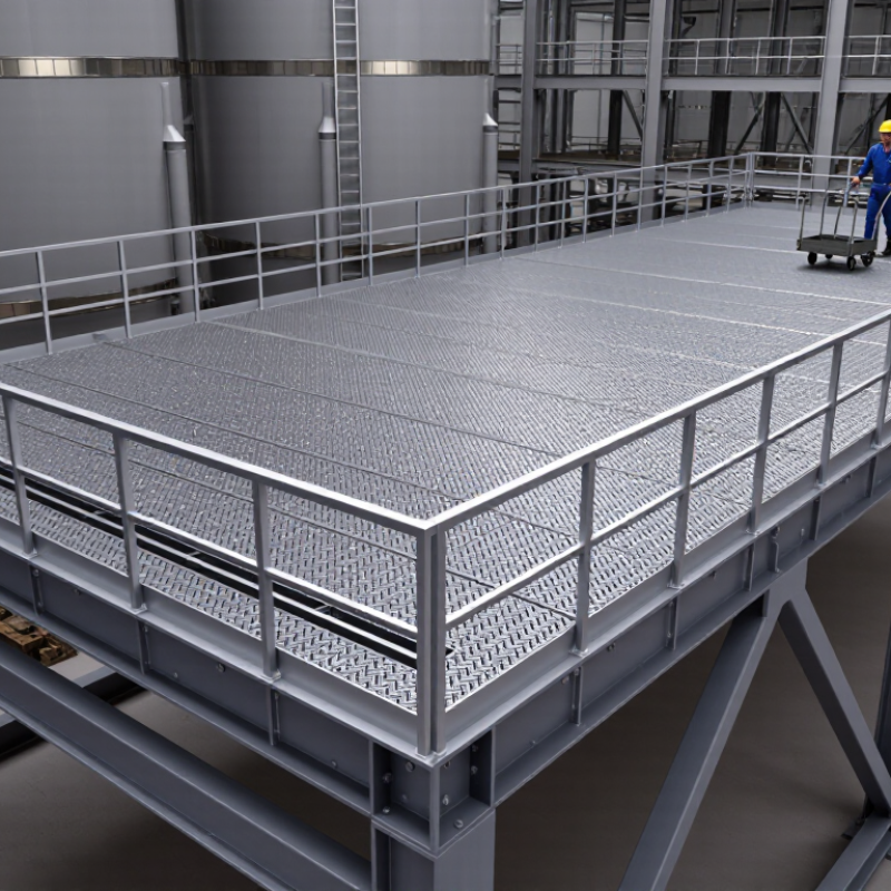
| Intended Use | Identify whether the grating is for a walkway, platform, stair tread, trench cover, equipment access area, or vehicle-access zone. | Walkways Platforms Stairs Drainage Covers | Different uses create different requirements for load, deflection, opening size, impact resistance, and access safety. | Record the use, expected traffic, equipment loads, and access restrictions in the design documents before selecting a panel type. |
| Design Load | Determine uniform live load, concentrated load, dead load, impact, and any moving or rolling load. | Common building design values may include a 4.8 kPa (100 psf) uniform live load for some occupied floors or walkways, but the governing code and project use control. | A panel that meets a uniform-load value may still fail under a concentrated wheel, foot, or equipment load. | Check manufacturer load tables or perform an engineering calculation for the actual clear span and load position. Inspect for permanent deformation after unusual loading. |
| Clear Span and Support | Measure the unsupported span, bearing width, support direction, and support elevation. | Panels are commonly supported on two opposite sides; bearing length is often specified by the engineer or project standard rather than assumed. | Span is a primary factor in bending stress and deflection. Incorrect bearing or orientation can substantially reduce capacity. | Confirm that support members are level, aligned, and strong enough. Do not cut, notch, or rotate load-bearing panels without engineering approval. |
| Bar Spacing and Openings | Select bearing-bar spacing and cross-bar spacing based on foot safety, tools, drainage, ventilation, and local code. | Typical industrial spacing may be 19, может 30, or 40 mm bearing-bar centers, with cross-bar spacing commonly around 100 mm; project requirements may differ. | Smaller openings improve pedestrian safety and reduce the risk of dropped objects, while larger openings may improve drainage and reduce weight. | Verify opening dimensions against the applicable building, workplace-safety, accessibility, and dropped-object requirements. Keep openings free of debris. |
| Material Selection | Match the base material to strength, temperature, chemical exposure, electrical conditions, and maintenance expectations. | Carbon Steel Stainless Steel Aluminum | Carbon steel provides high structural capacity; stainless steel supports demanding corrosive environments; aluminum reduces weight but has different strength and deflection characteristics. | Confirm alloy, temper, weldability, and compatibility with adjacent metals. Avoid direct contact between dissimilar metals where galvanic corrosion is possible. |
| Applicable Standards | Identify the standards used for design, fabrication, material, coating, welding, and installation. | Common references include ANSI/NAAMM MBG 531 for metal bar grating, ASTM A36 or ASTM A572 for certain carbon-steel products, ASTM A123 for hot-dip galvanized fabricated steel, and ASTM A780 for repairing damaged galvanized coatings. | Standards define terminology, tolerances, material properties, coating practices, and repair methods. They do not replace project-specific structural calculations. | Request material certificates, coating records, fabrication details, and installation instructions. Confirm the edition and jurisdictional acceptance of each standard. |
| Surface Finish | Choose a plain, serrated, galvanized, painted, or specialized corrosion-resistant finish. | Plain Surface Serrated Surface Hot-Dip Galvanized Painted | Serrated surfaces can improve slip resistance in wet or oily conditions. Coatings protect carbon steel but can wear at traffic points and cut edges. | Specify the required slip-resistance level and test method where applicable. Repair damaged galvanized areas using an accepted zinc-rich repair procedure. |
| Wet and Corrosive Exposure | Assess humidity, standing water, salt, chemicals, wash-down practices, soil contact, and atmospheric pollution. | Use drainage-friendly layouts, suitable galvanizing or stainless steel, and corrosion allowances where appropriate. Chemical compatibility must be checked individually. | Corrosion reduces cross-sectional area, weakens connections, creates sharp edges, and can eventually compromise load capacity. | Provide drainage and ventilation, eliminate water traps, and inspect regularly for rust, coating loss, pitting, and corrosion around fasteners and welds. |
| Slip Resistance | Evaluate footwear, liquids, oils, ice, mud, slope, and cleaning conditions. | Serrated bearing bars are commonly selected for improved traction in wet or contaminated areas; they are not a substitute for a complete fall-prevention design. | Slip risk depends on the surface, contaminant, footwear, walking direction, slope, and housekeeping—not only on the grating profile. | Use drainage, adequate lighting, handrails, toe boards, and routine cleaning. Replace severely worn or smoothened surfaces where required. |
| Panel Size and Handling | Balance panel dimensions with lifting access, installation space, transportation, and available labor or equipment. | Smaller modular panels simplify manual handling; larger panels reduce the number of joints but may require mechanical lifting. | Panels that are too heavy or large can create handling hazards and may be damaged during installation. | Confirm lifting points and temporary supports. Use safe lifting practices and never stand beneath a suspended panel. |
| Connections and Fasteners | Specify clips, saddle clamps, bolted connections, welds, or other approved restraints. | Connection design should account for uplift, vibration, thermal movement, lateral movement, and removal requirements. | Properly sized and placed connections prevent shifting, rattling, uplift, and progressive movement under traffic or vibration. | Install the specified number and type of fasteners. Check torque where applicable and inspect loose, missing, corroded, or damaged hardware. |
| Stair Treads | Check tread depth, width, nosing, slip resistance, attachment, and openings. | Stair geometry must comply with the applicable building and workplace-safety code; tread requirements are not determined by grating alone. | Unsafe rise-and-run dimensions, inadequate nosing, or excessive openings can cause trips and falls even when the grating is structurally adequate. | Verify uniformity of all treads, secure every tread, maintain visible edges where required, and replace distorted or loose treads promptly. |
| Cutouts and Penetrations | Coordinate openings for pipes, ducts, cables, columns, drains, and equipment bases before fabrication. | Large or irregular cutouts may require reinforced edges, additional support, trim angles, or a revised panel layout. | Unreinforced cutouts can interrupt load paths and create sharp edges or excessive unsupported spans. | Approve field modifications before cutting. Protect exposed edges, remove burrs, and restore corrosion protection after modification. |
| Deflection and Serviceability | Set an allowable deflection limit appropriate to pedestrian comfort, equipment operation, drainage, and appearance. | Many projects use serviceability limits such as span/240 or span/360, but the controlling limit must come from the design criteria or applicable code. | Excessive deflection may cause uncomfortable walking, ponding, vibration, equipment misalignment, or damage to finishes. | Verify the selected span/load combination using engineering calculations. Investigate noticeable bounce, sagging, or vibration before continued use. |
| Installation Tolerances | Confirm level, alignment, bearing, panel gaps, support contact, and transitions to adjacent surfaces. | Use the project specification or approved fabrication drawings for exact tolerances; avoid relying on visual fit alone. | Uneven panels and excessive gaps increase trip, wheel, tool-drop, and vibration risks. | Complete an installation inspection before opening the area to traffic. Correct rocking panels, unsupported corners, protruding fasteners, and unsafe gaps. |
| Routine Inspection | Establish inspection frequency based on traffic, exposure, criticality, and regulatory requirements. | Inspect before initial use, after severe weather or impact, and at periodic intervals appropriate to the environment; high-risk areas may require more frequent checks. | Early detection of corrosion, cracks, distortion, and loose connections reduces the chance of unexpected failure. | Document panel identification, condition, defects, photographs, corrective actions, and inspection dates. Restrict access when structural integrity is uncertain. |
| Cleaning and Drainage | Remove debris, oil, ice, sediment, and materials that block drainage or conceal defects. | Use cleaning methods compatible with the grating material and coating; avoid chemicals that attack the base metal or protective finish. | Blocked openings create standing water, increase slip risk, accelerate corrosion, and add unintended dead load. | Clean high-traffic and wet areas on a defined schedule. Keep drains and channels open and verify that wash water does not collect below the panels. |
| Replacement Criteria | Define when a panel, bearing bar, cross bar, fastener, or support must be repaired or replaced. | Replacement is generally warranted for critical section loss, cracked welds, severe deformation, unsafe openings, failed connections, or unresolved instability. | Cosmetic coating damage may be repairable, while loss of structural section or permanent distortion can require engineering evaluation or replacement. | Tag and isolate defective areas. Have a qualified person assess damage and approve repair, reinforcement, or replacement before reuse. |